PE flange connections must not and do not have to leak — a statement
For planners and users of PE pressure pipes, the use of ISO 9624 can lead to problems because the basic flange standard does not take essential aspects into account. It also does not help to use other plastic application standards such as EN 12201 and ISO 4427 (water) or EN 1555 (gas) because they refer to this ISO 9624. The alternative EN ISO 15494 (industry) deals with the flange topic independently but has not (yet) implemented compatibility with the steel standard EN 1092–1 as well. Irrespective of the ISO problem described in more detail below fully pressure-loadable, standard-compatible flange connections that have been optimised for plastic have therefore proven themselves in practice. The pressure load capacity is therefore made possible without restrictions for nominal pressures of 10 bar, 16 bar or even PN 25 or even higher.

Plastic flange connections: What are the limits?
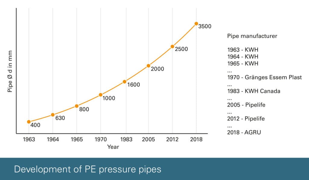
The raw material PE was developed in the 1960s and DIN standards for PE pipe joints were drawn up in the 1970s, which became the German standard in the 1980s and were partly used in this way worldwide. At that time, however, the application focus of plastic pipe systems was more on corrosion resistance than on operating pressure. It was therefore sufficient to use the standard steel loose backing rings as a basis for PE pipe systems, although the pipe diameters and also the wall thicknesses differed significantly from steel pipes. The plastic stub ends were pragmatically “adapted” to the backing rings in terms of dimensions and thus became the basis of the new DIN 16963–4 standard developed in 1988. The limited load-bearing capacity that resulted for some dimensions was even initially no problem for applications in the chemical industry. With increasing operating pressures around water supply for PE pressure pipe applications and, above all, nominal diameters far beyond DN 200 (picture 1), the limits of the load-bearing capacity of plastic flange connections became apparent in practice as early as the 1990s. Therefore, in 1996 Reinert-Ritz developed the fully pressure-loadable HP flange for PE pressure pipe systems. The triggering reason for this was a case of failure in which the DN 800 welding neck had ” jumped out ” from under the backing ring during the pressure test. With the development of raw materials to today’s PE100, the possible internal pressure load capacity increased again, so that in practice the weak point of standard flanges became increasingly obvious.

Figure 1: Leakage of a DN 600 pressure pipeline
The problem of ISO 9624
With the internationalisation of PE standards, the DIN 16963 flange standard used worldwide at the time was replaced in 1998 by the newly created first edition ISO 9624. However, as a compromise to other local standards at the time, important dimensions such as the stub end or flange thickness and other dimensions were dropped. The biggest problem with this internationalisation was the “lack of knowledge” of the ISO working group active at that time that in the British countries and colonies the PN 16 flange standard was used and the DIN standard was based on PN 10 flanges. Ignoring this problem meant that in practice planners and users automatically combined the PN 10 stub ends with the PN 16 backing rings used in UK countries. The technically necessary and sensible dimensional adjustments of the steel standard EN 1092–1 were therefore unknowingly not implemented when PN 16 flanges were used. Figure 2 clearly shows that with the ISO market standard, the contact area between the flange/ plastic stub end is proportionally very small and is quickly overloaded under the internal pressure load, incorrect bolt tightening torques and tends to “flow”.
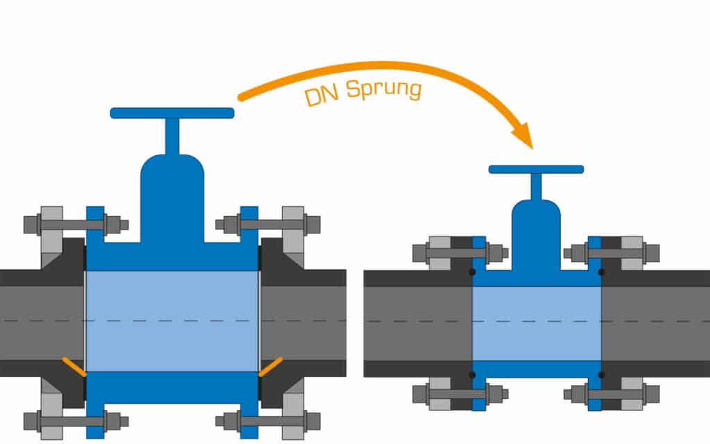
Figure 2: True-scale illustration of the PN 10 — PN 16-ISO problem at DN 600,
left ISO 9624, right analogue steel standard EN 1092–1
Why is this ISO not corrected?
The simple fact that a wrong basic standard was the unchanged wrong market standard used for more than 20 years as described shows the complexity of this question. The “market” knew about cases of damage, but these were not attributed to the wrong standardisation, but to other causes: flexible plastic, wrong assembly, wrong seal up to the last wrong material. The basic problem is that a realisation of the problem of faults cannot be corrected because no one is responsible at the “ISO”, although there are presently positioned directors for the areas of technique or quality. First of all, this is due to the “association structure” of the ISO, with responsibilities of persons who sometimes do not react when approached or who like to delegate responsibility to local country organisations, i.e. for Germany the DIN in Berlin. Berlin, however, refers to the “offer” to actively participate in this standardisation group. This goes on like the well-known ping-pong game until the ball runs out of energy…

A “nominal size April Fool’s joke” in the valid ISO 9624 basic standard
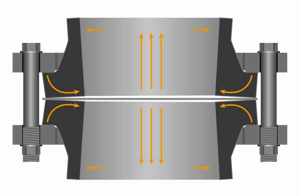
After more than 20 years of validity of the old ISO 9624 first edition, a revision of this flange basic standard appeared in 2019. This was not only to correct the PN 10 — PN 16 problem identified by a working group member, but also to address even PN 25 in addition to some other additions! Unfortunately, the PN 10 — PN 16 basic error shown in Fig. 2 was again fixed as standard because the majority of the working group did not support this necessary, “costly”, optimised dimensional adjustment. In their opinion, the dimensional adjustment was not needed because there were no technical problems on the market. During the revision of the standard, the working group interestingly took up a note that stated that with the pipe diameter d 630 mm, the contact between the stub end and the backing was critically small. This statement was technically correct, but in practice it did not lead to any problem even at nominal pressures beyond 10 bar if good profile gaskets and the market-known DVS screw tightening torques were used. As a solution to the problem, this working group proposed to use DN 700 backing rings instead of DN 600 flanges for d 630 mm (Fig. 3). This would have solved the problem of the old standard, if the PE stub end had also been logically adapted. However, as can be seen in Figure 3, the standard was ultimately adopted, with the wrong, larger backing ring, but with the old, smaller contact surface. Earlier “protests” about the planned change in nominal size, even from within the own working group, were not seen as technically justified. After the publication of the standard, Reinert-Ritz became active and informed some companies concerned by the standardisation error about the new ISO compatibility problem. At the same time, a proposal was made as to enlarge the contact area by 25 % without changing the nominal size. The proposed change was presented to the working group and adopted in January 2020.
Figure 3:
ISO 9624 — 2019:
DN 600 — d 630 mm has been changed to DN 700 — d 630 mm for “optimisation”.
ISO 9624 DN correction is again incorrect
In September 2021, after 19 months of implementation, the correction was published, but it was forgotten to correct the annex as well. A correction of the correction would be technically necessary and right, but was not supported by the working group, which is even understandable to some degree, because a new correction would take years and would not increase transparency either. A withdrawal with a following, corrected new edition would be the correct solution, but has not been done so far because the error was classified as minor. Thus, the faulty standard ISO 9624 with additional, wrong correction remains in circulation.
PE flange connections can also be made under extreme loads
Finally, I would like to point out that PE flange connections designed by engineers are already part of many impressive, pressurised water projects. The 70 km long DN 1500 PE pressure pipeline, which is floating freely through the Mediterranean Sea, can be seen as an example. Every 500 m, the pipeline, which floats by “nature”, is anchored to the seabed at a depth of 250 m. At the centre of this installation, two pairs of flanges form the connection between the PE and the steel anchor bends. The d 1600 mm pressure-loaded flange connections are under permanent bending load.
In addition, there is the influence of sea circulation and earthquake disturbances.
The example should show that with correct planning and design and taking into account the aspects explained in this article, PE flange connections can fulfil their function permanently without any problems — but one should not ignore the problems of ISO 9624.
Download the original paper of the 3Rs here (in German language)